Cotton growers who anticipate collecting yield data should take the time to check yield monitor components to ensure accurate data collection. Yield monitors are one of the most common precision agriculture technologies used today, ranked only behind GPS Guidance Systems currently on the farm. Proper calibration is key if management decisions, prescriptions, or profit maps are to be generated from yield data. It is important to note that using a yield monitor to evaluate decisions that were made throughout the growing season is an extremely valuable tool.1 Prior to calibration, it is critical to make sure the cotton picker is working properly. If the picker is not working properly during calibration and the problem is fixed during harvest, the calibration may not be representative, and another calibration may be needed.
There are two main brands of cotton yield monitors, John Deere and Ag Leader®; however, John Deere is the only cotton yield monitor currently available as a new purchase. These two types of yield monitors vary on how they sense the flow of cotton through the ducts of the cotton picker. The two types are categorized as a microwave sensor (John Deere) and an optical sensor (Ag Leader®). Each of these sensors quantifies the flow of cotton through the ducts, and from that sensor response, a cotton mass flow rate is calculated and is used along with field capacity (ac/hr) to calculate yield. Manufacturers and university researchers suggest, that once a cotton picker yield monitor is calibrated, additional calibrations may be needed if changes in varieties, moisture, quality of defoliation, irrigated vs. non-irrigated, or crop conditions occur.2
Cotton lint yield can fluctuate due to varying lint turnout percentages from varietal characteristics. It is important to note that yield data can be modified after harvest has been completed in order to account for these variations in lint turnout. By taking yield and fiber quality data that has been collected and post-calibrating it with computer-based software to incorporate additional data (e.g., turnout), yield and profit maps can have improved accuracy. Integration of RFID tracking technology, from the tagger on a John Deere round-bale module to the scanner on the feeder at the gin, will aid in the automating post-calibration process.
Prior to calibrating, keep a few things in mind: make sure the cotton picker is set up correctly, read the operators manual for the yield monitor, and check that the GPS offset and row unit swath width is set up properly. In addition, the following yield monitor components should be inspected and calibrated.
Pre-season Checklist
Optical or Microwave Mass Flow Sensors
For machines equipped with optical sensors (Ag Leader®), check to ensure that the lenses on the sensors on both the front and back of the ducts are clean and free of any debris or obstructions prior to harvest. Also, ensure that wiring harnesses and sensors themselves are not damaged and appear to be in working order.
Header Height Sensor (if equipped)
Check to make sure the sensor itself is intact and wiring to the sensor has not been damaged. While it may not seem important, if this sensor is not accurately reading when the header is lowered into the crop, data collection may be incomplete; most yield monitors use header height position as a recording trigger. John Deere systems have the option of setting the recording trigger to material flow (regardless of other factors), which generally works well.
Distance Calibration
Verify that the distance you are traveling is the distance that is being recorded. It is not a bad idea to recalibrate to make sure acreage recordings are accurate. Yield monitors calculate crop yield as a function of acreage rate (field capacity, ac/hr) and mass flow rate. Therefore, if your acreage rate is off by 20%, then your yield estimate is also likely to be off by 20%.
In-field Calibration
Calibrating the Mass Flow Sensor
A step-by-step guide for John Deere calibration on a 2600 or 2630 display is provided in the next section of this publication. Depending on the yield monitor manufacturer, you will likely need to flag loads as calibration before they are harvested. At minimum, two calibration loads should be used; one with a basket that is between one-fourth and half full and the other between three-fourths full and full. Ideally, four to five calibration loads should be used with different basket loads to ensure accurate calibration. Weigh each individual basket with a boll buggy equipped with load cells, a scale trailer (used for baler pickers), or a set of truck scales (weigh boll buggy or round module) that you know is accurate and record the weight. After each basket load has been harvested and weighed, the weights can be entered in the yield monitor display. Depending on the brand of the yield monitor, you may be required to enter each load weight after collecting each load, or you may be able to enter all five weights at the end. Make sure that the basket and air ducts are completely empty after each load is harvested. Should you have a newer CP690 (2017+) John Deere bale picker with module weighing capabilities, it is still important to calibrate this machine to ensure the weighing arm is correct.
After completing the six steps detailed below, the yield monitor should be calibrated and ready for harvest. It is also important to note that as harvest continues throughout the remainder of the season, a separate calibration may need to be completed to ensure the greatest accuracy when harvest switches to another variety or crop conditions change.
Examples of various yield monitor components are provided (figures 1 and 2). These pictures are for example only and do not represent every make and model of harvester or yield monitor component. Clemson University is not endorsing specific manufacturers of harvesters or yield monitor components. If you need assistance with yield monitor calibration, please contact your county Extension Agent (https://www.clemson.edu/extension/co/index.html). Clemson University has mobile platform scales to weigh round modules in addition to boll buggies with load cells to assist with calibration.

Figure 1. Optical Ag Leader® mass flow sensors on air duct; an additional sensor is located on the backside of the air duct. Image credit: John B. Wilkerson, University of Tennessee-Knoxville.
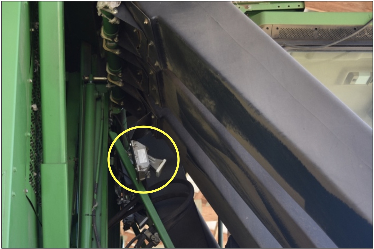
Figure 2. Microwave John Deere mass flow sensor on rear of air duct. Image credit: Michael Plumblee, Clemson University.
Cotton Yield Monitor Calibration Procedure for John Deere 2600 and 2630 Displays
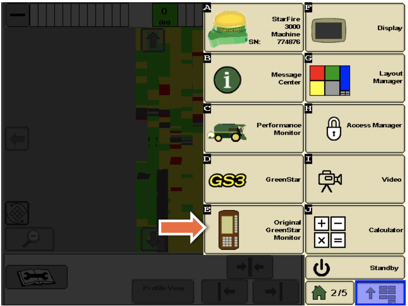
Step 1.
From the Menu screen, click the “Original GreenStar” Monitor” button.
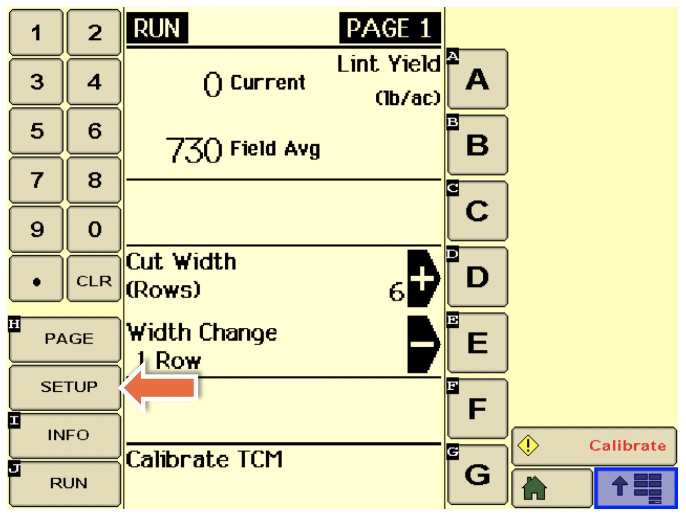
Step 2.
Click the “Setup” button.
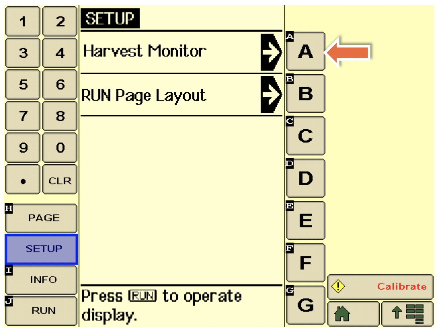
Step 3.
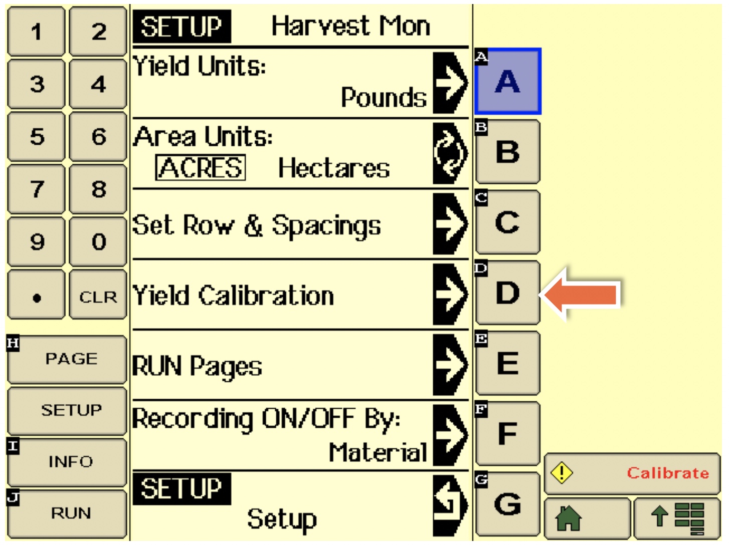
Click “A” for Harvest Monitor.
Step 4.
Set Yield Units and Acre units according to how you wish for them to be displayed on Run Screen, confirm “Row and Spacings” settings (spacing must be set for each row, a feature that allows support for skip row planting), then click “D” for Yield Calibration. Note: Recording trigger may be set at “F”. This is what controls starting and stopping of yield data collection.
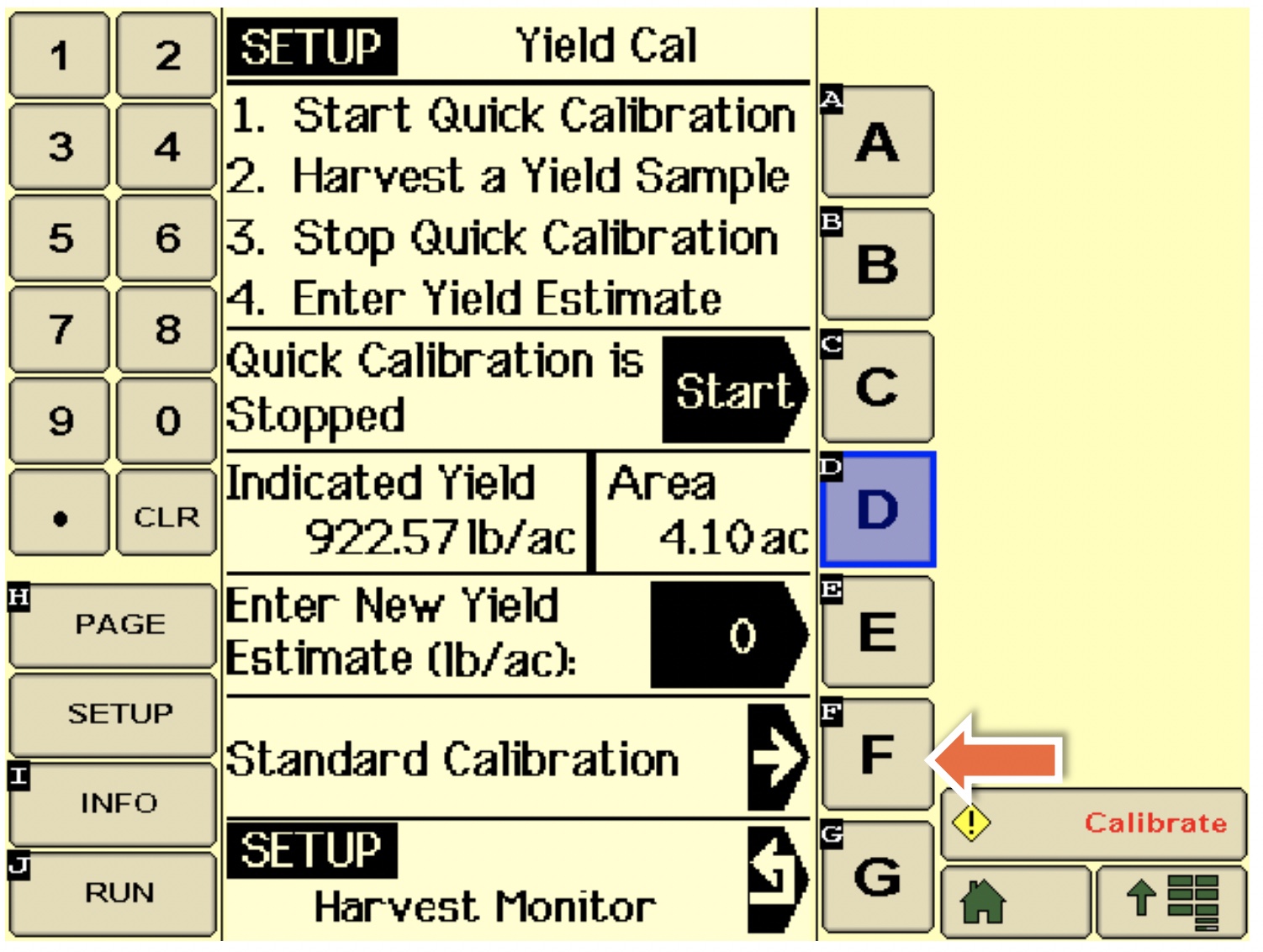
Step 5.
We recommend using the Standard Calibration procedure; click “F” for this option.
Step 6.
This is where the calibration begins. Once the Start button is clicked, an estimate of weight harvested (using existing calibration factor) is provided next to “C”. This value will continue to increase as cotton is harvested. After the calibration is complete, a known weight should be entered at “D”, which is used to update the calibration factor. Specific procedures vary dependent on the picker model.
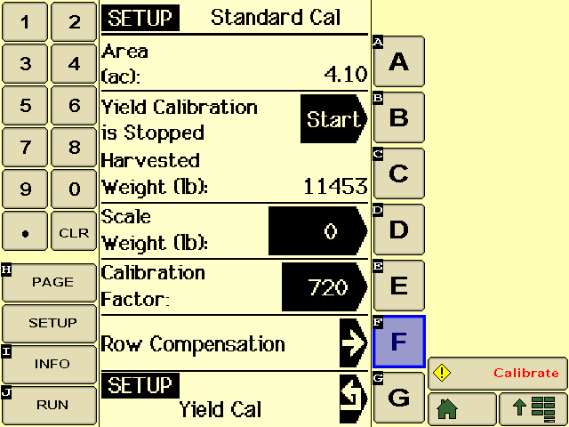
Basket Picker Instructions
Ensure that the basket is empty before proceeding. Then click “B” to start the calibration (Step 6). Once the desired amount of cotton is harvested (e.g., ½ basket), click the Stop button, which will appear at “B” after the calibration is started. Weigh this cotton and enter its weight at “D” to complete the calibration.
Round Module Picker Instructions
It is recommended that you use at least two round modules. This procedure is completed entirely while the picker is in motion (do not stop the picker to start or stop the calibration). At the moment that the armrest display indicates that a module is being wrapped (red markings on display), click the Start button at “B” (Step 6). The module being wrapped at this time is not a part of the calibration. Continue picking until the instant that wrapping begins on the next module. Make a note of where this module is set off in the field; it will be one of the calibration modules. We recommend continuing until at least two round modules are included in the calibration; make a note of where each one is set off in the field. At the instant that wrapping begins on the last module used in the calibration, click the Stop button at “B”. Weigh all the modules included in the calibration and enter the sum of the weights at “D” to complete the calibration.
References Cited
- Vellidis G, Barnes E, Brannen H. Cotton yield maps: tools for increasing efficiency & profitability. Cary (NC): Cotton Incorporated; 2017. https://www.cottoninc.com/wp-content/uploads/2017/03/Cotton-Yield-Maps-PDF.pdf.
- Vellidis G, Perry C, Wells T, Barnes E. Cotton yield monitors: the entrance exam & final exam for precision agriculture. Cary (NC): Cotton Incorporated; 2017. https://www.cottoninc.com/wp-content/uploads/2017/03/cottonyieldmonitors.pdf
References Consulted
Harvest Monitor Cotton Calibration Manual. Moline (IL): Deere & Company, John Deere; 2010. http://manuals.deere.com/omview/OMPFP10724_19/CZ76372,0000182_19_20100924.html.
Cotton Harvest Insert. InSight™ Firmware Version 6.0. Ames (IA): Ag Leader®; 2002. https://knowledgebase.agleader.com/kbp/index.php?View=afile&EntryID=1548&AttachID=776.