One of the more challenging aspects of developing pasture and grazing land is providing access to a reliable water supply for livestock. In some cases, existing streams, creeks, or ponds provide drinking water for the livestock. When a surface water source is not available, wells can be drilled and pumps installed to provide water for the animals. In some instances, surface water may be available, but not accessible to the livestock due to water quality issues, steep access slopes, or fencing issues.
Providing an electrical power source to such a location for a pump can be cost-prohibitive. Utilizing a pump powered by an internal combustion engine can require inspection and attention several times each day and regular fuel supply runs. Nose pumps and sling pumps may be used effectively in some of these situations, but these pumps will not work if the elevation difference between the water source and grazing area is greater than twenty feet. Solar-powered pumps are an excellent option but can be expensive depending on the flow rate and pressure needs of the system.
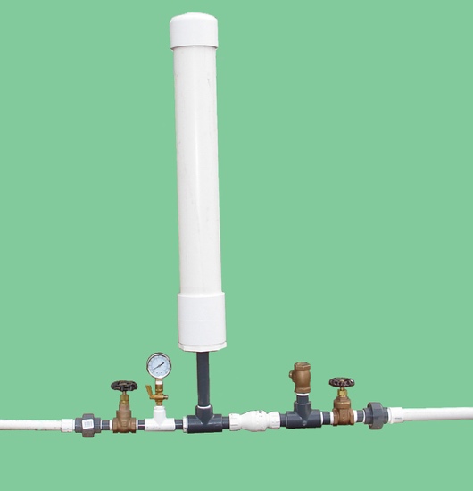
Figure 1. A 3/4-inch homemade hydraulic ram pump made with PVC fittings. Water flows from right to left during operation. Image credit: W. Bryan Smith, Clemson University.
One possible solution to providing livestock drinking water in remote locations is the hydraulic ram pump. The first development work of the hydraulic ram is reported to have been completed by John Whitehurst in 1772, with the first automatic version of the hydraulic ram developed by Joseph Montgolfier in 1796.1 Various companies in England and the United States have been producing cast-iron versions of the hydraulic ram since the early 1800s. Hydraulic ram pumps can lift water over a considerable elevation, and do not require any external power source.
Commercially sold hydraulic ram pumps last for decades but are quite expensive. A simple, homemade PVC (polyvinyl chloride) hydraulic ram pump (figure 1) may be constructed for $150 to $200 depending on material costs in your area and size of pump constructed. These homemade pumps will last for several years if not longer and can allow a farmer to see how such a pump would work before investing in a more expensive commercial unit.
Hydraulic Ram Pump Operation
Hydraulic ram pumps operate by utilizing pressure developed by a “water hammer” shock wave. Any object in motion has an inertial force. Energy is required to place the object in motion, and energy will also be required to stop the motion, with more energy being required if the motion is started or stopped quickly. A flow of water in a pipe also has inertia (or momentum) that resists sudden changes in velocity. Slowly closing a valve allows this inertia to dissipate over time, producing very little pressure increase in the pipe. Closing a valve very rapidly will create a pressure surge or shock wave as the flowing water stops, which moves back up the pipe – much like a train stopping, with individual train cars hitting the coupling in front of them in rapid succession as the brakes are applied. The more quickly the valve is closed, the larger the shock wave produced. A faster water flow will also produce a larger shock wave when a valve is closed, since more inertia or momentum is involved. A longer pipe will also produce a larger shock wave for the same reason.
A hydraulic ram relies on a non-pressurized flow of water in a pipe placed from the water source to the pump (called a “drive” pipe). This flow is produced by placing the hydraulic ram some distance below a water source and running the drive pipe from the water source to the pump. The hydraulic ram employs two check valves, which are the only moving parts in the pump.
Step-by-step illustrations are provided in figures 2-6 explaining how a hydraulic ram pump operates.
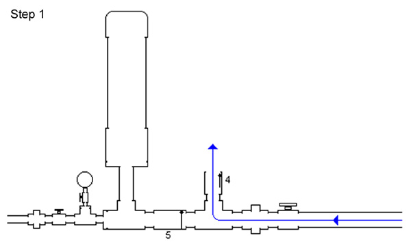
Figure 2. Step 1: Water (blue arrows) starts flowing through the drive pipe and out of the “waste” valve (#4 on the diagram), which is open initially. Water flows faster and faster through the pipe and out of the waste valve. Image credit: W. Bryan Smith, Clemson University.
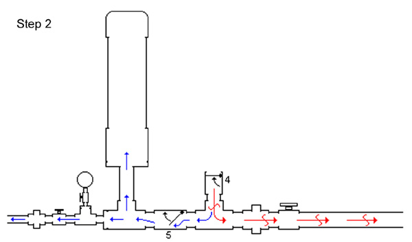
Figure 3. Step 2: At some point water is moving so quickly through the waste valve (#4) that it pushes the valve’s flapper up and slams it shut. The water in the pipe was moving quickly and had considerable momentum, but all the water weight and momentum is stopped by the valve’s closure. That creates a high-pressure spike (red arrows) at the closed waste valve. The high-pressure spike forces some water (blue arrows) through the check valve (#5 on the diagram) and into the pressure chamber. This increases the pressure in that chamber slightly. The pressure “spike” in the pipe also begins moving away from the waste valve and up the drive pipe (red arrows) at the speed of sound and is released at the drive pipe inlet. Image credit: W. Bryan Smith, Clemson University.
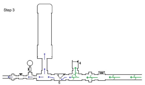
Figure 4. Step 3: After the high-pressure wave reaches the drive pipe inlet, a “normal” pressure wave (green arrows) travels back down the pipe to the waste valve. The check valve (#5) may still be open slightly depending on backpressure, allowing water to enter the pressure chamber. Image credit: W. Bryan Smith, Clemson University.
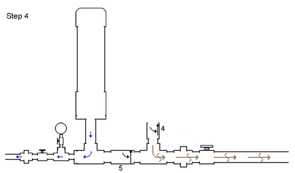
Figure 5. Step 4: as soon as the normal pressure wave reaches the waste valve, a low-pressure wave (brown arrows) travels up the drive pipe, which lowers the pressure at the valves and allows the waste valve to open and the check valve (#5) to close. Image credit: W. Bryan Smith, Clemson University.
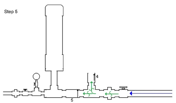
Figure 6. Step 5: When the low-pressure wave reaches the drive pipe inlet, a normal pressure wave travels down the drive pipe to the valves. Normal water flow due to the elevation of the source water above the ram follows this pressure wave, and the next cycle begins. Image credit: W. Bryan Smith, Clemson University. The hydraulic ram pump cycle described in figures 2-6 may repeat from forty to ninety times per minute depending on elevation drop to the hydraulic ram pump, drive pipe length from the water source to the ram pump, and drive pipe material used. Image credit: W. Bryan Smith, Clemson University.
Typical Hydraulic Ram Pump Installations
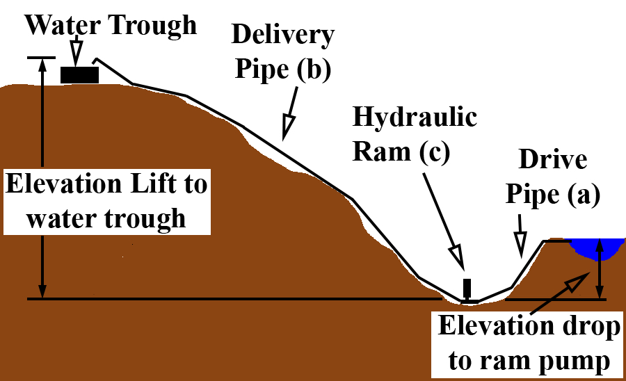
Figure 7. A typical hydraulic ram pump installation, with (a) drive pipe, (b) delivery pipe, and (c) hydraulic ram pump placement noted. Image credit: W. Bryan Smith, Clemson University.
In its simplest form, a hydraulic ram pump installation includes a drive pipe to bring water from the water source to the pump, the hydraulic ram pump, and a delivery pipe to take water from the pump to the water trough or site where water is needed (figure 7).
The drive pipe size determines the actual pump size and also determines the maximum flow rate that may be expected from the pump. Since the pump efficiency depends on capturing as much of the water hammer shock wave as possible, the best drive pipe material for a hydraulic ram pump installation is galvanized steel pipe. Most livestock producers use PVC pipe instead due to the lower cost and the difficulty in placing and assembling galvanized steel pipe. Hydraulic ram pump installations using a PVC drive pipe will work well, but the elasticity of the pipe will allow some of the water hammer shock wave to dissipate slightly with pipe wall expansion. If PVC pipe is used for the drive pipe installation, choose PVC piping with a thicker wall. Schedule 80 PVC pipe would be the better choice, with Schedule 40 PVC pipe being a secondary choice.
The best drive pipe installation would place the pipe on a constant slope from the water source to the hydraulic ram pump, with no bends or elbows, and anchor it with bolts and/or galvanized tie-downs to large rocks or concrete pads to prevent movement. This would allow the most efficient shock wave development. The Gravi-Chek Company suggests the optimum drive pipe slope is one foot of drop for every five feet of length, which corresponds to a 20% slope.2 However, this is not always practical in livestock water supply installations. The ram pump will work with piping that is not installed on a constant slope, as long as all piping slopes are either level or downward toward the pump (figure 8). There can be no “humps” or up-and-down installation points in the drive pipe, since this will allow air to be captured in the pipe, which will allow shock wave dissipation.
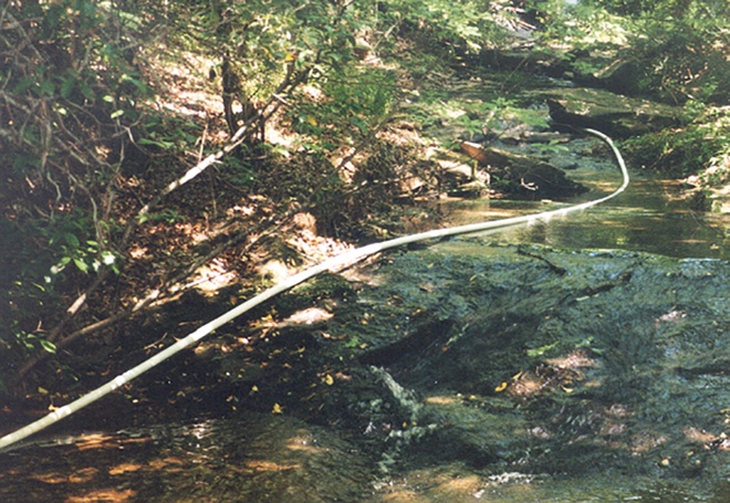
Figure 8. A PVC drive pipe placed in a stream bed. Galvanized steel was not an option due to the bed topography and geometry. The hydraulic ram pump worked well, but each bend allowed a tiny portion of the shock wave to dissipate. A straight, galvanized steel pipe would have captured a larger shock wave and provided more pressure. Image credit: W. Bryan Smith, Clemson University.
If a choice must be made between installing the drive pipe on a constant slope and using a more rigid drive pipe (such as galvanized steel), choose the more rigid drive pipe. This will have a larger impact on pump performance than the drive pipe slope.
The inlet of the drive pipe should be installed at least six inches below the water surface. If the inlet is installed just below the water surface, the rush of water into the pipe during the start of each cycle may create a vortex or whirlpool that can draw air into the pipe. This vortex action usually takes more time to develop than the half-second to one-second cycle time expected, but it could develop. It is also a good idea to place some type of screen made into a large ball or globe (twelve inches or more in diameter) over the drive pipe inlet to help exclude debris, small amphibians, and small fish. The large size of the screen will prevent restriction of the water flow into the pipe and can also help prevent vortex development.
There is a range of allowable drive pipe lengths for each pipe size used. If the drive pipe is too short or too long the pressure wave that allows the pump to cycle will not develop properly.
The publication Hydraulic Rams for Off-Stream Livestock Watering gives the following equations developed by N. G. Calvert for minimum and maximum drive pipe length.3
Minimum Drive Pipe Length:
L = 150 x drive pipe diameter
Maximum Drive Pipe Length:
L = 1000 x drive pipe diameter
For instance, if a 1-inch drive pipe were used, the minimum recommended length would be (150 x 1” =) 150 inches or 12.5 feet; the maximum recommended length would be (1000 x 1” =) 1000 inches or 83.3 feet. Table 1 provides a sample of minimum and maximum drive pipe lengths for various drive pipe sizes.
Table 1. Minimum and maximum recommended drive pipe lengths based on drive pipe diameter (rounded to full feet).
| Drive Pipe Diameter (inches) | Minimum Length (feet) | Maximum Length (feet) |
| 3/4 | 10 | 62 |
| 1 | 13 | 83 |
| 1 1/4 | 16 | 104 |
| 1 1/2 | 19 | 125 |
| 2 | 25 | 166 |
| 2 1/2 | 32 | 208 |
| 3 | 38 | 250 |
| 4 | 50 | 333 |
Rife Ram Company literature offers a different method of drive pipe length selection.4 The Rife method does not consider pipe size but is based solely on vertical elevation drop or fall from the water source to the hydraulic ram pump. Values are presented in table 2.
Table 2. Recommended drive pipe lengths based on elevation fall.
| Elevation Fall (feet) | Drive Pipe Length (feet) |
| 3-15 | 6 times vertical fall |
| 16-25 | 4 times vertical fall |
| 26-50 | 3 times vertical fall |
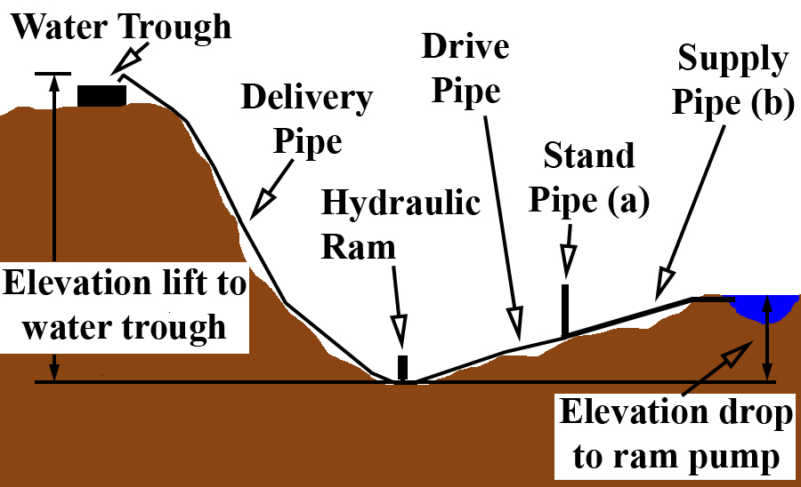
Figure 9. A hydraulic ram pump installation with a (a) standpipe and (b) supply pipe to allow a longer piping solution from water source to ram pump location. Image credit: W. Bryan Smith, Clemson University.
The Rife recommendations in table 2 maintain a given pipe slope for each range of elevation falls. Either method (table 1 or table 2) may be used to determine mainline length; satisfying both methods may provide the best ram pump performance.
There are installation solutions if the maximum drive pipe length allowed is not long enough to reach the water source from the hydraulic ram pump placement. One option is to install a “standpipe” at the maximum drive pipe distance from the ram pump (figure 9). This standpipe should be three pipe sizes larger than the drive pipe and should be open at the top to allow the water hammer shock wave to dissipate at that point. The standpipe should be installed vertically, with the top of the standpipe a foot or so above the level of the water source. Supply piping, which should be at least one pipe size larger than the drive pipe, is then run from that point to the water source.
Determining Elevation Drop or Fall
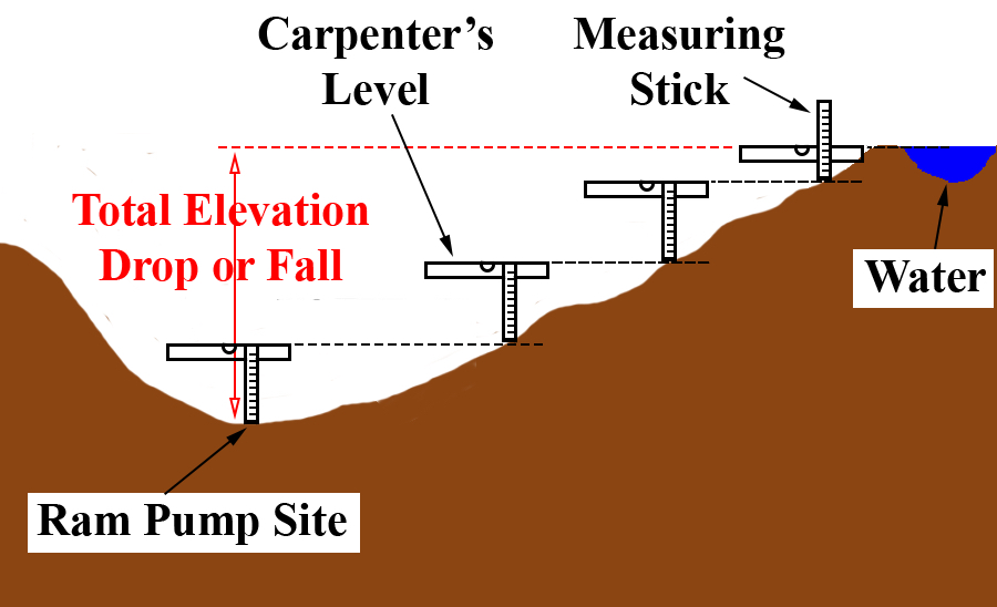
Figure 10. Use of a carpenter’s level and a measuring stick to determine elevation drop from the water source to the proposed hydraulic ram pump location. Image credit: W. Bryan Smith, Clemson University.
Hydraulic ram pumps operate based on an amount of elevation drop or fall from the water source to the site where the ram pump is placed. The amount of drop will determine the performance of the ram pump. The amount of drop or fall available at a given location can be measured using a measuring stick and a carpenter’s level. Start at the site where the hydraulic ram pump will be placed. Hold the measuring stick vertically, placing one end on the ground. Place the carpenter’s level on the measuring stick, holding it level, with the top even with the top of the measuring stick. Look along the top of the carpenter’s level at the slope going up to the water supply, and sighting along the top of the level, pick a spot on the slope (figure 10). That point is the height of the measuring stick above the starting point. Move to that spot and repeat the sighting process, continuing up the slope after each sighting until the water supply is reached. Count the number of times the measuring stick was placed on the ground, multiply that number by the measuring stick’s length, add any partial stick measurement for the last sighting (see figure 10), and the result will be the elevation drop or fall from the water source to the ram pump location.
Hydraulic Ram Pump Capacity
Hydraulic ram pumps are very inefficient, generally pumping only one gallon of water for every eight gallons of water passing through the ram. They will, however, pump water up ten feet (or more in some cases) of vertical elevation for every foot of elevation drop from the water source to the hydraulic ram. For instance, if there is an elevation drop of seven feet from the water source to the hydraulic ram, the user can expect the hydraulic ram to pump water up to seventy feet or more in vertical elevation above the ram. Higher delivery elevations do decrease the pump flow – the higher the elevation difference between the hydraulic ram and the delivery pipe outlet, the smaller the delivered water flow will be.
Rife Hydraulic Engine Manufacturing Company literature gives the following equation for calculating hydraulic ram pump flow.4
D = 0.6 x Q x F/E
In this equation, Q is the available drive flow in gallons per minute, F is the fall in feet from the water source to the ram, E is the elevation from the ram to the water outlet, and D is the flow rate of the delivery water in gallons per minute. 0.6 is an efficiency factor and may differ somewhat between various ram pumps. For example, if a flow rate of twelve gallons per minute is available to operate a ram pump (Q), the pump is placed six feet below the water source (F), and the water will be pumped up an elevation of twenty feet to the outlet point (E), the amount of water that may be pumped with an appropriately-sized ram pump is:
0.6 x 12 gpm x 6 ft / 20 ft = 2.16 gpm
The same pump with the same drive flow will provide less flow if the water is to be pumped up a higher elevation. For instance, using the data in the previous example but increasing the elevation lift to forty feet (E):
0.6 x 12 gpm x 6 ft / 40 ft = 1.08 gpm
The pump inflow rate, Q, will always be determined by the drive pipe size, drive pipe length, and the elevation of the water source above the hydraulic ram.
Table 3 uses the Rife equation to list some flow rate ranges for various sizes of hydraulic ram pump based on the friction loss found in Schedule 40 PVC pipe. The pump flow ranges in the chart are based on a fall (F) of five feet of elevation and an elevation lift (E) of twenty-five feet. Changing the values of E or F will change the expected performance of the ram pump.
Table 3. Typical homemade hydraulic ram flow rates.
| Drive Pipe Diameter (inches) | Delivery Pipe Diameter (inches) | Minimum Pump Inflow (gpm) | Expected Output (gpm) | Maximum Pump Inflow (gpm) | Expected Output (gpm) |
| 3/4 | 1/2 | 0.75 | 0.10 | 2 | 0.25 |
| 1 | 1/2 | 1.5 | 0.20 | 6 | 0.75 |
| 1 1/4 | 3/4 | 2 | 0.25 | 10 | 1.20 |
| 1 1/2 | 3/4 | 2.5 | 0.30 | 15 | 1.75 |
| 2 | 1 | 3 | 0.38 | 33 | 4 |
| 2 1/2 | 1 1/4 | 12 | 1.5 | 45 | 5.4 |
| 3 | 1 1/2 | 20 | 2.5 | 75 | 9 |
| 4 | 2 | 30 | 3.6 | 150 | 18 |
Note: The values are based on twenty-five feet of lift and five feet of elevation fall.
Some of the delivery flow rates listed in table 3 are quite small, but even the 3/4-inch ram pump will deliver a considerable amount of water over time. Hydraulic ram pumps operate twenty-four hours per day, seven days per week, so even at the minimum pump inflow the 3/4-inch ram pump will provide (0.10 gpm x 60 minutes x 24 hours =) 144 gallons of water per day, which would supply the daily water need of four to five 1,200 pound cattle.
If more flow is desired, either a larger hydraulic ram may be used, or another hydraulic ram may be installed with a separate drive pipe, and then plumbed into the same delivery pipe to the water trough as long as there is sufficient water flow in the water source to supply this demand.
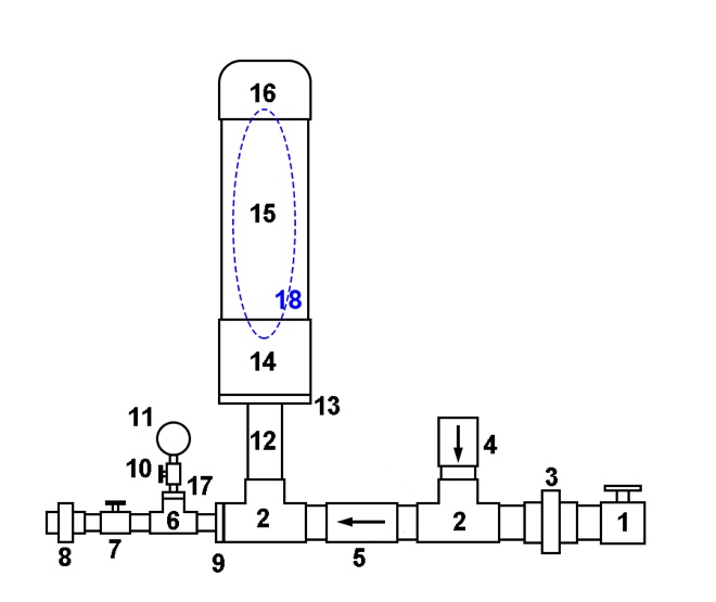
Figure 11. A schematic diagram for homemade hydraulic ram pump Design 1. Table 4 contains item descriptions. Image credit: W. Bryan Smith, Clemson University.
The Homemade Hydraulic Ram – Design 1
There are a number of designs for a homemade hydraulic ram. The University of Warwick has some excellent designs developed for use in developing countries where standard plumbing parts may not be readily available.5
This publication will address two similar designs. The first design was developed by Mark Risse of the University of Georgia and was presented by Frank Henning in University of Georgia Extension Service publications #ENG98-0023 and #ENG98-003.6 Figure 11 provides a schematic of the design, and table 4 provides a parts list for a 1 1/4-inch hydraulic ram pump.
Table 4. Materials descriptions for the hydraulic ram pump presented in figure 11.
| Item Number | Description | Item Number | Description |
| 1 | 1 1/4” valve | 10 | 1/4” pipe cock |
| 2 | 1 1/4” tee | 11 | 100 psi gauge |
| 3 | 1 1/4” union | 12 | 1 1/4” x 6” nipple |
| 4 | 1 1/4” brass swing check valve | 13 | 4” x 1 1/4” bushing |
| 5 | 1 1/4” spring check valve | 14 | 4” coupling |
| 6 | 3/4” tee | 15 | 4” x 24” PR160 PVC pipe |
| 7 | 3/4” valve | 16 | 4” PVC glue cap |
| 8 | 3/4” union | 17 | 3/4” x 1/4″ bushing |
| 9 | 1 1/4” x 3/4” bushing | 18 | Inner tube (inside 15) |
This is a very simple design that only requires assembly of basic plumbing fittings. The air chamber (#14–16) acts like a pressure tank for a well, using compressible air captured in the tank to buffer shock waves and provide a steady outlet pressure. The air initially captured in this air chamber, however, will be absorbed by the water flowing through the pump over time. When this happens there will be a much more pronounced shock to the pump and piping during each cycle (this condition is described as a water-logged pump), and material fatigue and failure will follow. In order to keep air in the chamber over time, a bicycle or scooter inner tube may be filled with air until it feels “springy” or “spongy,” and then folded and inserted into the pressure chamber before the cap (#16) is glued on to the pipe. This will retain air in the chamber and prevent pump failure.
Fittings 1–4 in the diagram must be the same size as the drive pipe in order for the pump to work properly. The spring-loaded check valve (#5) and the pipe nipple (#12) should also be the same size as the drive pipe, but the pump should work if they are reduced to the same size as the delivery pipe.
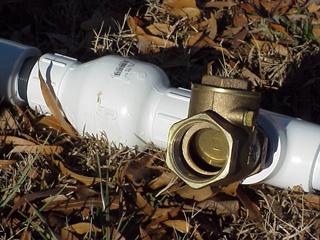
Figure 12. A brass swing check valve. Note the free-swinging flapper in the outlet port. The swing check valve should be placed vertically for best pump performance. Image credit: W. Bryan Smith, Clemson University.
The waste valve (#4) is a brass swing check valve. This valve must be brass or another type of metal to give the flapper enough weight to prevent premature closure. The flappers on similar PVC valves weigh very little and close under lower flow conditions, preventing development of a higher-pressure shock wave. This valve cannot be a spring-loaded type of check valve but must have a free-swinging flapper as shown in figure 12.
The second check valve in figure 11 (#5) should be a standard, spring-loaded poppet-style check valve. This valve may be made of PVC or brass.
Valve #1 in figure 11 is used to stop or allow flow to the pump and can be used to turn off water flow if the pump needs to be removed or serviced. Valve #7 is turned off while the pump is started, then gradually opened to allow water to flow after the pump is operating. The pump will operate for thirty seconds or more with this valve completely closed, and if the valve is left in the closed position the pump will reach some maximum pressure and stop operating. The ram pump requires approximately 10 psi of back pressure to operate, so if the delivery pipe outlet is not at least twenty-three feet above the ram pump, valve #7 can be used to throttle the flow and maintain the required back pressure.
The pressure gauge (#11) is used to determine when valve #7 may be opened during pump start-up and can be used to determine how much valve #7 should be closed during normal operation if throttling is needed. The pipe cock (#10) is optional but can be turned off to protect the gauge from failure over time due to repeated pulses.
The air chamber size is dictated by the expected flow rate of the hydraulic ram pump. University or Warwick documentation suggests the optimum pressure chamber volume is twenty to fifty times the expected volume of water delivery per cycle of the pump.5 Table 5 provides some minimum lengths of piping required for a pressure chamber based on this information. The table is based on a hydraulic ram that will operate sixty pulses or cycles per minute.
Table 5. Minimum suggested air chamber sizes for homemade hydraulic ram pumps.
| Drive Pipe Size (inches) | Expected Flow per Cycle (gallons) | Air Chamber Volume Req. (gallons) | 2-inch Air Chamber Length (inches) | 3-inch Air Chamber Length (inches) | 4-inch Air Chamber Length (inches) |
| 3/4 | 0.0042 | 0.21 | 15 | 7 | — |
| 1 | 0.0125 | 0.63 | 45 | 21 | — |
| 1 1/4 | 0.020 | 1.0 | 72 | 33 | 19 |
| 1 1/2 | 0.030 | 1.5 | 105 | 48 | 27 |
| 2 | 0.067 | 3.4 | — | 110 | 62 |
| 2 1/2 | 0.09 | 4.5 | — | 148 | 85 |
| 3 | 0.15 | 7.5 | — | 245 | 140 |
| 4 | 0.30 | 15 | — | — | 280 |
Note: The table values are based on a ram pump operating at sixty cycles per minute.
The Homemade Hydraulic Ram – Design 2
The second design presented in figure 13 is one commonly found on the internet in YouTube videos.7 It is very similar to the first design, but this design incorporates a homemade “snifter” valve that allows a small amount of air to be added to the air chamber with each pumping cycle, which eliminates the need for an inner tube in the air chamber.
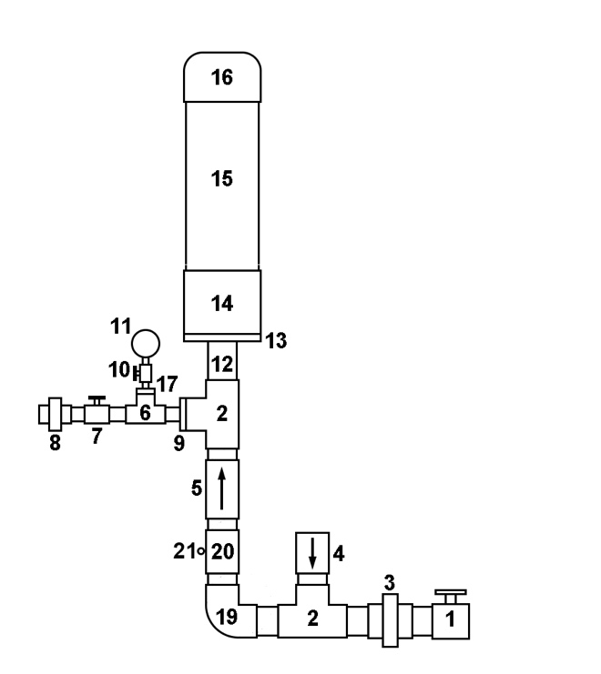
Figure 13. A schematic diagram for homemade hydraulic ram pump Design 2 with air snifter. Tables 4 and 6 contain item descriptions. Image credit: W. Bryan Smith, Clemson University.
The item descriptions in table 4 also apply to this design. Three additional items needed for this design are listed in table 6.
Table 6. Additional materials descriptions for hydraulic ram pump Design 2 presented in figure 13.
| Item Number | Description |
| 19 | 1 1/4” elbow |
| 20 | 1 1/4” coupling |
| 21 | cotter pin |
The difference in the two designs is the vertical placement of the spring-loaded poppet check valve (#5) just below the air chamber, and the addition of a small hole in the vertically-oriented coupling (#20) just below that check valve (some designs suggest drilling the hole in the lower part of the check valve instead, below the flapper). A cotter pin (#21) is placed in the hole to reduce water loss (and pressure loss) to some degree when a pressure cycle occurs, but still allow air to be drawn into the pipe to be pushed into the air chamber in the next cycle. Fitting size and material information are the same as for Design 1 except for the following: pipe coupling (or nipple) #20 used for the snifter hole should be galvanized steel to prevent wear by the cotter pin over time, and galvanized steel is a better material choice for elbow #19 for structural strength.
The size of the snifter hole is critical to pump operation. The University of Warwick has an extensive discussion concerning this property in their hydraulic ram pump documentation.5 Their information suggests drilling a 1/16-inch hole and increasing the size slightly if necessary. A 1/8-inch snifter hole or smaller with an appropriately sized cotter pin inserted may be a good option instead as a starting point. If the hydraulic ram should become waterlogged, a slightly larger snifter hole may be needed.
The advantage of this design is that if the snifter hole is sized correctly, the pump should never become waterlogged due to a leaking inner tube in the air chamber. The disadvantages are the trial-and-error approach to obtaining the correct hole size, the need for additional support for the pump’s increased vertical height, and the possibility that the snifter hole, being very small, may freeze over and close in cold weather.
Pump Operation
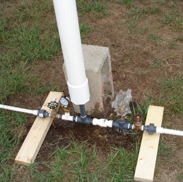
Figure 14. A 3/4-inch hydraulic ram pump (Design 1) in operation. The image was taken just at waste valve closure. The concrete block is in place to support the air chamber. Image credit: W. Bryan Smith, Clemson University.
Both pump designs are started using the same steps. Attach the assembled ram pump to the drive pipe, close valve #7, then open valve #1 to allow water flow. The waste valve (#4) will almost immediately forcefully close. The flapper in the waste valve must be pushed down manually a number of times to initially start automatic pump operation. This process purges air from the system and builds up the pressure in the air chamber required for the pump to operate. Pressing the flapper down twenty to thirty times is expected to start a ram pump. If the pump does not start operating after pressing the flapper down more than seventy times, there is an issue somewhere in the system. The flapper on a smaller pump (1/2-inch, 3/4-inch, etc.) can be pressed down with a thumb fairly easily, but larger pumps may require the use of a metal rod of some type to push the flapper down, especially if there is considerable elevation drop between the water source and the hydraulic ram pump.
After the pump has started operating (figure 14), gradually open valve #7 to allow water to flow uphill to the water trough. The pump must have 10 psi or more back pressure to operate, so gradually open valve #7 while watching the gauge to maintain 10 psi of back pressure. Pressure will build as the water fills the delivery pipe as it is pumped uphill.
The pump will operate continuously after starting as long as water flows freely to the pump and is flowing out of the delivery pipe. If water flow is stopped at the water trough, the ram will pump up to some maximum pressure and stop, and then must be manually restarted. The pump will not restart itself. This means that if water is supplied to a single water trough, a float valve cannot be used. Some provision must be made to drain overflow away from the trough after it fills, since the water must flow continuously for the pump to remain in operation. A simple gravel-filled trench or another method may be used to direct the excess water away from the water trough.
Since water continuously flows out of the pump’s waste valve, some consideration must also be given to water drainage at the pump site. If the pump is placed near a stream downstream of a pool or other water source, this will not be an issue. If, however, it is placed on dry ground away from the water source, drainage must be considered.
Delivery Pipe Materials and Sizing
There are no restrictions on the size or type of delivery pipe used beyond normal piping design practice. Galvanized steel pipe, PVC pipe, rubber hose, or a simple garden hose may be used to deliver water to the water trough, provided it is sized to deliver the anticipated flow rate. Some ram pump installation guidelines indicate the delivery pipe should be one half the size of the drive pipe, but this has no bearing on the pump performance. The delivery pipe should be sized based on flow rate and friction loss.
Table 7 provides some maximum recommended flow rates for various pipe sizes. These flow rates are based on a maximum flow velocity of five feet per second in the delivery pipe, which will help prevent water hammer development in the delivery pipe. Smaller flows than those listed will allow the water to be piped longer distances or to higher elevations within reason, since less pressure will be lost to pipe friction. Pipe friction loss charts for the appropriate pipe material used may be utilized to determine the actual friction loss for a given installation.8 Larger delivery pipes will reduce friction losses but will also increase costs. Smaller delivery pipes will cost less but can decrease the ram pump flow rate. If friction losses are not calculated, use half the allowable flow rates (or less) listed in table 7 to select a delivery pipe size.
Table 7. Recommended maximum flow rates for various sizes of Schedule 40 PVC piping, based on a flow velocity of 5 feet per second.
| Pipe Size (inches) | Max. Flow Rate Schedule 40 (gpm) | Pipe Size (inches) | Max. Flow Rate Schedule 40 (gpm) |
| 1/2 | 5 | 2 | 56 |
| 3/4 | 9 | 2 1/2 | 82 |
| 1 | 16 | 3 | 123 |
| 1 1/4 | 27 | 4 | 205 |
| 1 1/2 | 35 |
Suitable Water Sources for a Hydraulic Ram Pump
Water will run continuously through a hydraulic ram pump since the pump runs constantly. If the water source for the pump is a shallow pool in a flowing stream or creek this will not be an issue, since water flows continuously in those water bodies. There may be a problem, though, if a small pond is used as a water source for a hydraulic ram pump.
For example, say that a farmer decides to use a small, 1/2-acre pond to supply a hydraulic ram. The pond history shows that it seems to stay fairly full except during times of severe drought. The farmer wants a flow rate of 1 gpm (gallons per minute) to his livestock water trough, and therefore places a 1 1/2-inch hydraulic ram pump behind the pond. The ram pump requires a flow of approximately 9 gpm to produce the desired 1 gpm flow to the water trough.
The ram pump runs twenty-four hours per day, seven days per week, withdrawing 9 gpm from the pond. This flow rate will remove (9 gpm x 60 minutes x 24 hours =) 12,960 gallons of water per day from the pond. That is the equivalent of approximately one inch of water removed from the pond each day. If the stream or spring that fed the pond was just adequate to keep the pond full before the ram pump was installed, the pond water level will begin to fall one inch each day. Over a month’s time the pond level could fall as much as thirty inches.
There are methods described in the next section that allow the use of a hydraulic ram pump using a pond as a water source without breaching the dam. The farmer, though, must first determine if the springs or streams supplying the pond will be adequate to maintain the pond’s water level before installing a ram pump. This may prevent draining a good pond to non-useable levels.
Pumping from a Pond
If a hydraulic ram pump is installed behind a pond dam, the farmer should also consider drainage requirements to remove the expelled drive water from behind the pond. This will prevent the development of a wet area or possible soil erosion over time.
Some type of siphon assembly may be used to draw water from a pond and deliver it over the dam to a hydraulic ram pump. However, this siphon cannot be directly connected to the drive pipe without some provision for pressure and siphon release. The siphon will interfere with the development of the pressure wave in the drive pipe. If a siphon is used, the water may be delivered by the siphon pipe to a trough or barrel open to the atmosphere behind the pond dam, with a ram drive pipe plumbed directly into the trough or barrel. This will prevent the siphon action from affecting pressure wave development.
Pump Maintenance
There are only two moving parts in the home-made hydraulic ram pump – the waste valve and the spring-loaded check valve (#4 and #5 in figures 11 and 13). Over time one or both of these valves may fail simply due to wear. The wear will be more extensive in rams utilizing sandy or silty water, and in rams that have a more rapid cycle time. Farmer reports indicate that home-made hydraulic ram check valves seem to last between three months and two years depending on these two factors. The two unions in the figures 11 and 13 (#1 and #8) are there to allow pump removal for maintenance if needed.
If there is detritus in the water source and an inlet screen is not used, there may be an issue with a small stick or twig becoming caught between the waste valve flapper and the valve seal, preventing proper valve closure. In some cases, this might make it miss a cycle and then the stick may be flushed away, but in other cases the stick may become lodged. If the hydraulic ran pump is the only source of water for your livestock it should be checked daily – in most cases the farmer can simply drive near the site, roll down a window (or turn the tractor off), and listen for the regular “click” to confirm the pump is operating. The best inspection is always to visit the operating pump, but a second option is simply to visit the water trough to make sure water is flowing.
If a ram pump is used during winter months, care should be taken to insulate as much of the pump and above ground piping as possible. The constant flow of water through the pump should help prevent freezing, but ice may still build up around the waste valve outlet in colder temperatures and might stop the pump. If Design 2 is used, inspection of the snifter hole is a must in cold weather to ensure it has not frozen closed.
If a hydraulic ram pump is installed in or near a small stream bed, care should be taken to make sure the pump is anchored sufficiently to a concrete pad or other heavy, non-moveable items to prevent loss during a major storm event. Some type of shield or shelter from branches or other detritus flowing downstream during such an event should also be considered. A better placement would be to position the ram pump on dry ground near the stream, but out of the potential flood plain for average storm events, with drainage provisions for the waste or drive water to return to the stream.
“Tuning” The Pump
There are two methods that may be used to “tune” or adjust a hydraulic ram pump to increase or decrease pump pressure and flow rate. The first tuning method is to simply change the position of the waste valve (#4 in figures 11 and 13). This valve should normally be placed vertically for best pump performance. If the grower desires to lower the pressure, the tee the valve is attached to (#2 in figures 11 and 13) may be rotated slightly to one side, which will allow the waste valve flapper to drop slightly into the valve body. The valve body should be oriented as shown in figure 12 to allow the flapper to descend into the water flow path. Rotating the valve slightly will allow the flapper to close at a slower water velocity, which will create a smaller water hammer shock wave and result in a lower pump pressure. Rotating the valve too far, as illustrated in figure 12, will cause the pump to stop operating, since the water velocity in the drive pipe will be too slow when the valve closes to create a useful water hammer shock wave.
The second tuning method can be used to increase the pressure developed by the ram pump, and in doing so increase the flow rate. The waste valve flapper (shown in figure 12) will close when a certain water velocity is reached in the pipe. The weight of the valve flapper determines the water velocity needed to close the flapper. If weight is added to the flapper, a higher water velocity will be necessary to close the flapper. The University of Warwick’s “How Ram Pumps Work” publication provides a detailed description on flapper weights and closing water velocities.9
Common methods of increasing flapper weight include using screws or epoxy to attach washers or other small weights to the flapper. Care must be exercised to attach weights so that they remain firmly attached and they do not interfere with normal valve closure. The grower must also consider how much pressure may be obtained by tuning the pump in this manner. It is possible to increase the water velocity in the pipe to where the increased water hammer shock wave may cause actual damage to the piping or the pump.
Common Problems
The Ram will not start: (a) In most cases this is due to the fact that the correct size check valve for the waste valve was not installed. That valve and tee must be the same size as the drive pipe. Using a PVC check valve or a metal check valve that is spring-loaded instead of a free-swinging check valve will also cause this issue; (b) Another problem could be a lack of elevation difference between the ram pump and the water source. While some commercially made ram pumps will operate with as little as twenty inches of elevation fall, these home-made units are less efficient and require approximately five feet of vertical elevation drop to operate dependably; (c) the air has not been purged from the system. Pushing the waste valve flapper down twenty to fifty times is normal to start a hydraulic ram pump; (d) a flexible hose was used for the drive pipe. The drive pipe must be made of a rigid material.
The ram pumps for a few cycles and stops: (a)This is usually due to a drive pipe that is too long or too short for the hydraulic ram pump size. A drive pipe that is too long or too short can interfere with or prevent the development of the shock wave pulse in the pipe; (b) valve #7 on the outlet side of the pump is not closed when starting the pump. This valve must be closed during start up for the pump to develop some back pressure and start operating.
We tested it with a garden hose, but it would not start. Sliding a garden hose inside the drive pipe to supply water to test the ram will partially pressurize the water in that pipe, which will interfere with the water hammer shock wave and keep the waste valve closed. The best way to test a hydraulic ram pump is to plumb the drive pipe to the bottom of an open bucket and keep the bucket filled with water from the garden hose. The bucket should be a minimum of five feet in elevation above the ram.
The ram starts pulsing very hard and then stops. This is usually due to an inner tube not being placed in the air chamber during construction, but in some cases the air chamber may have developed a crack or sharp edge may have worn a hole in the inner tube. Air-tight seals in glued PVC pipe connections two inches in size and larger require the use of both PVC primer and PVC cement during assembly. Use of both primer and cement is also recommended for smaller PVC pipe sizes.
Conversion Factors and Definitions
1 inch (1”) = 2.54 centimeters
1 pound per square inch (1 psi) = 6.895 kPa
1 pound per square inch (1 psi) = 0.06895 bar
1 gallon per minute (1 gpm) = 3.78 liters per minute
1 foot of elevation head = 0.433 psi (for water)
1 acre = 0.4047 hectare
For comparison with locally available piping, 1-inch Schedule 80 PVC pipe has a minimum wall thickness of 0.179 inches and has a rated working pressure of 630 psi; 1-inch Schedule 40 PVC pipe has a minimum wall thickness of 0.133 inches and has a rated working pressure of 450 psi.
References Cited
- Green and Carter Ltd., 2013. Somerset, England: Green and Carter Ltd; c2013 [accessed 2019 July]. http://www.greenandcarter.com/main/about_us.htm.
- Gravi-ChekTM. San Diego (CA): CBG Enterprises [accessed 2019 July]. http://www.gravi-chek.com/html/installation.html.
- Henning F, Risse M, Segars W. Hydraulic rams for off-stream livestock watering. Agricultural Engineering Department, University of Georgia. 1998; ENG98-002.
- Rife manual of information. Nanticoke (PA): Rife Hydraulic Engine Manufacturing Company; 1992.
- School of Engineering. Technical release: TR12 – DTU P90 hydraulic ram pump. Design technical unit (DTU) ram pump programme. Coventry (UK): University of Warwick. [updated 2008 July 25; accessed 2019 July]. https://warwick.ac.uk/fac/sci/eng/research/grouplist/structural/dtu/pubs/tr/lift/rptr12.
- Henning F, Risse M, Segars W, Calvert V, Garner J. Hydraulic ram made from standard plumbing parts. Agricultural Engineering Department, University of Georgia. 1998; ENG98-003.
- Home built model hydraulic ram pump. Dieseljonnyboy. 2012 Apr 21, 7:53 minutes. [accessed 2019 July]. http://www.youtube.com/watch?v=4OmYsS2lHPY.
- Irrigation Association. Tools and calculators: Irrigation Association friction loss charts. Fairfax (VA): Irrigation Association; c2019 [accessed 2019 July]. https://www.irrigation.org/IA/Resources/Tools-Calculators/IA/Resources/Tools-Calculators.aspx.
- School of Engineering. Technical release: TR15 – How ram pumps work. Coventry (UK): University of Warwick. [updated 2008 July 25; accessed 2019 July]. https://warwick.ac.uk/fac/sci/eng/research/grouplist/structural/dtu/pubs/tr/lift/rptr15.
References Consulted
Roberson JA, Crowe CT. 1980. Engineering fluid mechanics second edition. Boston (MA): Houghton Mifflin Company.
Stanley J. 2013. Personal communication.