Proper Soil Sampling
Soil testing provides farmers with the current nutrient and pH status of their soils and also provides fertilizer and lime recommendations based on the crop to be grown in that field. This is a critical component in any forage or cropping system. However, any farmer will tell you that traditional soil sampling is a time consuming, labor-intensive process if done correctly. Agronomists recommend that fifteen to twenty soil “cores” be taken from random spots in each 10-acre (or smaller) section of a given field or pasture, which are then mixed together to produce a single composite sample that provides an accurate representation of the soil nutrient status of that area. Pulling that many soil cores per field over many fields can wear even the most hardy worker down, especially if the soil is dry or hard.
“Sweatless” Soil Sampling
Several years ago, the Soil, Water, and Forage Analytical Laboratory of Oklahoma State University developed a “Sweatless Soil Sampler” (figure 1).1 This soil sampler utilizes a Long Ship Auger-type wood drill bit, a cordless electric drill, and a simple pail to take soil samples. This revolutionary idea provided a way to obtain soil sample cores without the physical effort required when using conventional soil probes, spades, or shovels. It also allowed the farmer to collect all of the soil cores from an area in the pail before having to transfer them to the soil sample bag or box to be sent to the laboratory.
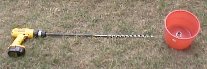
Figure 1. The original Oklahoma State University Sweatless Soil Sampler. Image credit: Oklahoma State University.
There was, however, no way to accurately gauge how deeply the drill bit was going into the soil when obtaining a soil core. Many soil testing labs recommend that tilled or plowed areas be sampled to a 6- to 8-inch depth, which is a normal tillage depth. They also recommend that pastures, hay fields, and no-till areas be sampled only to a 4-inch depth, since any lime applied to correct soil pH in those situations will require a considerable amount of time to move down through the soil profile by water movement alone. The general idea is that if deeper soil cores are taken in these areas, the resulting soil tests will result in recommendations of lime additions for one or more years after the required amount of lime has been initially applied, which may result in over-application of lime and corresponding issues due to a high pH soil in the upper three to four inches of the soil profile.
The Modified “Sweatless” Soil Sampler
Modification of the Oklahoma State University design to accurately gauge soil core depth is a relatively simple process. Adding a length of 3/4-inch Schedule 40 PVC pipe to limit the depth of travel of the drill bit into the soil, with exit holes near the bottom of the pipe for the removed soil core, provides an accurate soil depth measurement or gauging device.
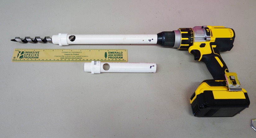
Figure 2. Completed PVC pipes used in the first design to limit sampling depth (one 4-inch depth; one 8-inch depth). Note the single hole which will allow soil to exit into the pail when installed. Image credit: W. Bryan Smith, Clemson University.
The simplest method to determine the length of PVC piping required is to first slide a length of it firmly into a 3/4-inch Schedule 40 PVC male adapter (this may be simply friction-fit together instead of glued, since there will be no pressure and little force on the unit). Next, attach the Long Ship Auger to the drill to be used, and place the unit on a table beside the pipe and male adapter assembly. Move the pipe assembly until the end of the male adapter is the desired soil core depth above the drill bit end and mark the pipe just at the end of the drill chuck. Cut the pipe at this point and the length is set for that particular drill bit and cordless drill (figure 2).
The soil exit holes can be made by carefully drilling a 3/4-inch hole through the PVC pipe just above the male adapter. Be sure to properly secure the pipe unit in a vise before drilling to prevent injury.
After the PVC pipe is drilled, 1-1/8-inch holes are drilled in the bottom of a pail to accept the 3/4-inch PVC male adapters, which are secured in place with conduit nuts (figures 3 and 4).
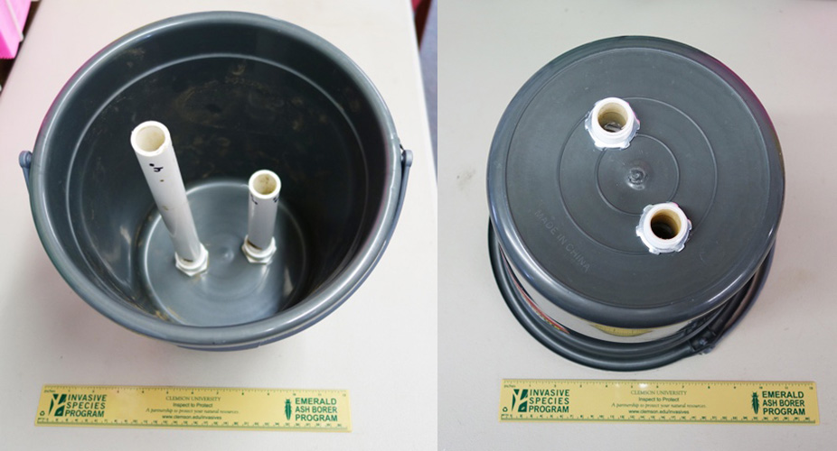
Figure 3. Completed modified sweatless soil sampler with single exit hole in the PVC pipes. This model has two sampling tubes installed, one for a 4-inch sampling depth, and another for an 8-inch sampling depth. Note the conduit nuts on the bottom of the pail holding the male adapters in place. Image credit: W. Bryan Smith, Clemson University.
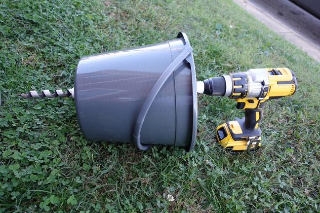
Figure 4. Completed unit showing the drill bit extending four inches past the male adapter after the drill chuck comes in contact with the PVC pipe. Image credit: W. Bryan Smith, Clemson University.
The 3/4-inch holes in this design provided an easy exit point for dry soils (figure 5). However, several clients noted that if heavier soils with some moisture in them – not mud, but “plow moisture” soils – were sampled, repeated sampling could leave a thin layer of heavy soil into the PVC pipe and cause a rotation stress or torque on the pipe. This caused the PVC pipe to spin while sampling. The clients addressed the issue by gluing a cross-bar or tee-bar arrangement to the soil sampling device that could be held, which kept the PVC pipe from rotating (see figure 6).
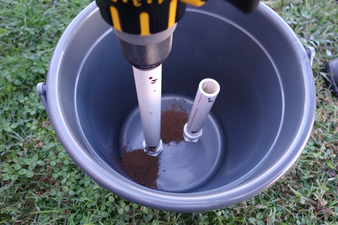
Figure 5. The completed original single-hole unit in operation, showing dry soil exiting the pipe from the holes on both sides of the PVC pipe. Image credit: W. Bryan Smith, Clemson University.
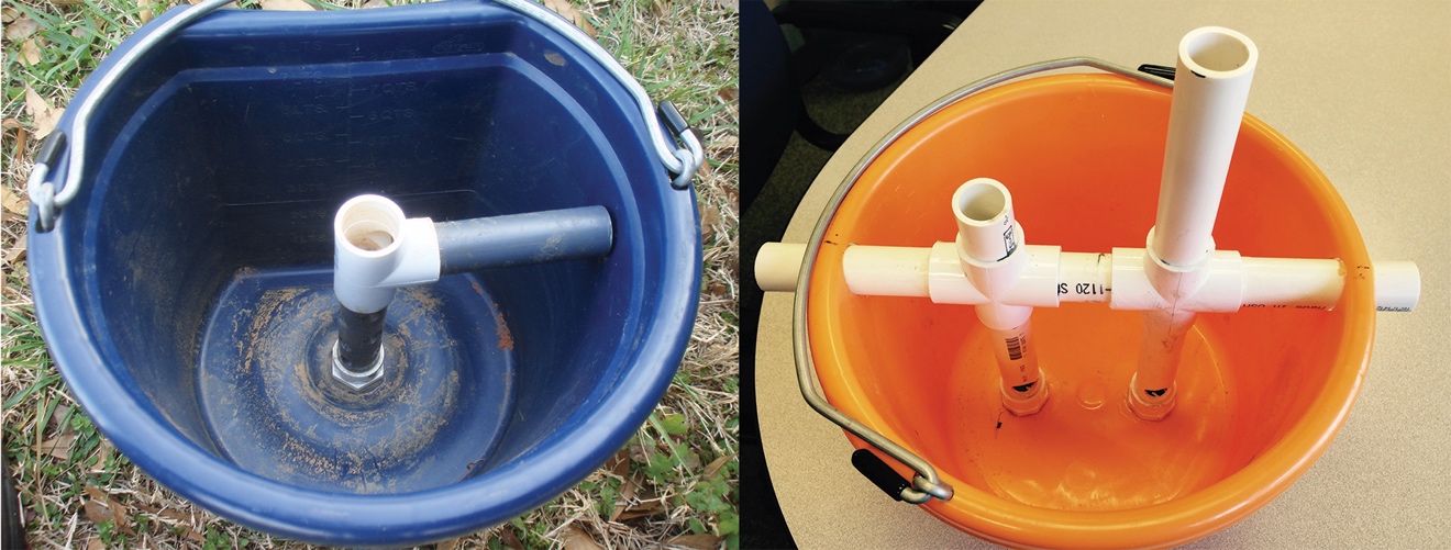
Figure 6. Client modifications to prevent PVC pipe from spinning when sampling moist soils. The side handle is held while sampling (image on left). This design has multiple soil exit holes. Image Credit: Reed Edwards, Laurens County Cattleman. Another design has two sampling depths and pipe through the pail sides for stability (image on right). This design has single soil exit holes. Image credit: RD Morrison, Oconee County Cattleman and Lindsey Craig, Clemson Extension Service Livestock and Forages Agent.
A larger exit hole design was then developed to alleviate this torque. A 3/4-inch hole saw was used to drill two holes completely through the PVC pipe approximately three inches apart on center, and a band saw was used (a jigsaw or coping saw could be used if the pipe is secured properly in a vise) to remove the side of the PVC pipe between the holes (figure 7). This created a 3-inch-long hole on each side of the PVC pipe, which allows a much larger area for soil to exit the pipe and leaves less pipe wall for the soil to compact against to cause torque. PVC crosses were used in the updated design like the ones in the client modifications in case there was any torque on the pipe with moist soils (figure 8).

Figure 7. Two 3/4-inch holes were drilled in the pipe with a hole saw. A band saw was then used to remove material between the holes drilled to provide a larger soil exit point. Image credit: W. Bryan Smith, Clemson University.

Figure 8. A completed long hole two-depth pipe assembly ready to be inserted in the pail with crosses in place in case torque on the PVC pipe occurs. Note the labels on each pipe noting the soil sampling depth. Image credit: W. Bryan Smith, Clemson University.
The “long exit hole” idea was field tested beside one client’s tee-bar, single exit hole assembly in a lush, mixed legume/grass pasture in April. The soil moisture was approximately plow moisture level. Repeated soil cores were taken in similar locations across the field in both units. The client had used 3/4-inch Schedule 80 PVC pipe he had on hand to assemble his unit (which has a thicker wall and therefore a smaller inside diameter than Schedule 40 pipe) and was also using a 5/8-inch Long Ship Auger drill bit instead of a 3/4-inch bit. A layer of soil residue built up inside the PVC pipe of the client’s unit after repeated samples (figure 9), which induced a torque on the pipe while sampling. The client had added more soil exit holes to his unit since first constructing it and noted that even though there was torque on the pipe, the torque was less than before. Even with the additional holes, soil seemed to be plugging some of the holes after extended use (figure 10).
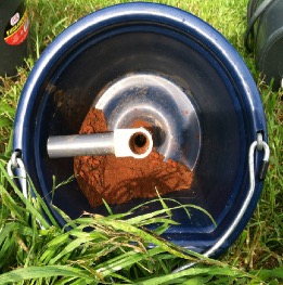
Figure 9. Image showing the soil buildup inside the pipe in the client’s tee-bar style unit, using a 5/8-inch Long Ship Auger drill bit and 3/4-inch Schedule 80 PVC pipe. Excessive wall-to-bit clearance was a factor. Image credit: W. Bryan Smith, Clemson University.
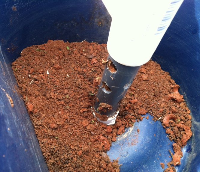
Figure 10. Even with multiple soil outlet holes, this design showed plugging issues in the 3/4-inch Schedule 80 PVC pipe, which possibly also contributed to the soil layer deposit in the pipe. Image credit: W. Bryan Smith, Clemson University.
The long exit hole unit, using 3/4-inch Schedule 40 PVC pipe and a ¾-inch Ship Auger drill bit, worked satisfactorily during the test (figure 11) with very little torque induced (holding the edge of the bucket lightly was sufficient to prevent spin). Soil did not appear to build up inside the tube (figure 12), partially due to the ease of soil exit with the larger hole and partially due to the closer clearance between the 3/4-inch drill bit and the PVC pipe wall. Soil may build up over time based on client observations, but in the approximately 20-core test, there was little noticeable soil buildup.
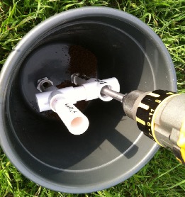
Figure 11. The long hole exit unit in use. This unit has two pipes to allow both 4-inch and 8-inch deep soil sampling. Note the soil exit holes are facing the pail sides, not the adjacent pipe, to prevent soil loss through the pipe not being used. Image credit: W. Bryan Smith, Clemson University.

Figure 12. Both units were used to sample an equivalent number of soil cores. This design not only showed no torque force on the pipe, but also showed little sign of soil buildup inside the pipe. Image credit: W. Bryan Smith, Clemson University.
Based on the field test, the long exit hole design is recommended. Clients with dry or lighter soils may find the single exit hole design satisfactory, but if not, another hole can easily be added to the existing unit and the material removed between the two holes.
If all the soil sampling on your farm will be in pastures, hay fields, and no-till fields, a single pipe and male adapter assembly (with a cross pipe in case of twisting) placed in the pail to allow a 4-inch sampling depth will be sufficient. If, however, your farm also has tilled fields, adding another pipe and male adapter unit that allows the drill bit to penetrate to a 6- to 8-inch depth in the same pail is a simple process. Be sure to mark the depth of sampling on each pipe with a permanent marker in this case to prevent confusion.
The Long Ship Auger drill bit works well but, will obviously wear over time. The drill bit works well for 150 soil cores or more in hard, dry, Cecil Sandy Loam soil eroded to the B horizon, and considerably longer in softer, moist soils. The drill bit becomes harder to push into the soil as the drill bit dulls, until, at last, it will only dig a short way into the soil. The drill bit should be replaced (or sharpened if possible) at that point.
Drill battery life has not been an issue. A single 4 amp-hour lithium ion battery unit will sample more than 150 cores in soft, moist soils; in hard, dry Cecil Sandy Loam soils eroded to the B horizon, the drill used one 4 amp-hour lithium ion battery’s full charge and approximately half of a second battery’s charge to sample 160 cores.
Modified “Sweatless” Soil Sampler Construction
Tools required:
- Electric or cordless drill
- 3/4-inch Long Ship Auger drill bit
- 1-1/8-inch hole saw (for pail bottom)
- 3/4-inch hole saw (for soil exit hole)
- Hacksaw or pipe saw
- Band saw or coping saw
Materials required:
- Small pail (sturdier pails with thicker walls and flat bottoms are better)
- 3/4-inch Schedule 40 male adapter
- ~12 inches of 3/4-inch Schedule 40 PVC pipe (length depends on drill bit length)
- 3/4-inch tee or cross (depending on design preference – one or two pipe model)
- 3/4-inch conduit nut
- PVC cement
References Cited
- Oklahoma State University. Stillwater (OK); Soil, Water, and Forage Analytical Laboratory; 2019.
http://soiltesting.okstate.edu/samples-and-testing/soil-sampling-tools.